Sunday, October 21, 2012

VE3IAC/2 et l'île Verte

Welcome.

IOTA NA-128 is an island group in the Quebec province of Canada in the St Lawrence Seaway. IOTA indicates that this island group is well claimed by 43% of participants. l'île Verte is one of many islands in this group which includes a 350km stretch of the St Lawrence Seaway.

NA-128 Island Group
With your help we completed 153 QSOs. My thanks goes to all who answered my "CQ de VE3IAC/2 IOTA NA-128" call. I realize that pileups can be hard to get through, and I appreciate your patience.

QSOs
From a volume perspective, notable QSOs are all of those from Europe and Middle East. I am always amazed how many operators there are in Germany.

New for me was Iceland, Aegir Olafsson TF2CT, many 73s to you.

Noel Hammond ZR6DX of South Africa at 12600km was especially nice, 599 both ways.

I must not forget 9000km South America stations in Argentina Horacio Cortadello LU6EHO and Dani Grezzi LW1DG.

The operation station included a Yaseu FT2000D Transceiver running 200W SSB through a Palstar AT1500CV Tuner into a twin lead fed DX Engineering 80m Doublet. 50watts was run on 10m and 20m with a YP-3 Portable Yagi .

VE3IAC/2 Operating Station at Ilse Verte NA-128
The station also used a Icom 756 Pro III Transceiver running 100W SSB through an Icom AH-4 Tuner into the twin lead fed DX Engineering 80m Doublet.

VE3IAC/2 Operating Station at Ilse Verte NA-128
YP-3 setup for 10m Operation
The view facing Europe.
Lighthouse on the North Shore

Here is a link from the last time we were here.
http://acomeau.blogspot.ca/2010/04/iota-activation-of-na-128-by-ve3iac2.html

73 OM
Adrien
VE3IAC/2

Monday, February 27, 2012

2012 Silent Lake DX expedition

Hi OM

Thanks for visiting, this post is for another trip to Silent Lake. This trip was especially nice for a few reasons. My work takes me away from home on occasion, and I had just returned from Stockholm. Roxanne and I love time we spend together and this was a nice way to slow down a bit and enjoy each others company. On the other hand, the real reason, (but don't tell her!) is that I get to play radio once again.


Silent Lake is a provincial park in the central south Ontario. 


This park has a number of Yurts for daily rental, more information on these can be read at http://www.ontarioparks.com/english/silentyurt.html . The more notable items that are provided by the park at each Yurt are;
  • Two sets of bunks beds, sleeping 6 or more (depends on how cozy you want to be!)
  • Heating is by wood burning stove, with a endless supply of wood that splits very easily 
  • Propane barbecue, this is truly nice.  
  •  


Entry into the park, starts with your personal vehicle but does not end there, because you can not drive to the yurts, even though the yurts are on the normal campground road system. The park Ranger takes you and your stuff the last 1 to 2 km into the park with a ride in a mini bombardier and a pair modified sleighs.


At the site we were welcomed the next morning by a doe and her two yearlings. The park ranger  had told us that there was a threesome that was wandering the park, but for the past few days, they had not seen them all together. It was nice to see that nothing had happened to them.


I'd have to say with ears like those there is no wonder you only see them if they want.


 On the radio front, the important bits of the setup was the usual stuff.
I would expect that most folks are familiar with the IC-7000. I like the radio very much, it gets a bit hot at times and can use a bit of extra cooling at times. This is simply done with a 3in muffin fan.

IC-7000 100W Transceiver
The AH-4 tuner is another cool (especially in the winter time!) piece of equipment. It connects to the IC7000 with two connections. RF coax, and a 4 wire control link. It is activated, and powered from the IC7000. I have used this unit for both random wire end fed and in this case feeding a balanced system.

Icom AH-4 Tuner

The antenna I have used on this trip as well as a few others is a 80m doublet. It is twin lead fed (about 90ft) to the main part of the antenna which is about 130ft in total length. The connection is a bit different from the usual description in the manual which focuses on unbalanced feed lines. I am sure there are other ways to do this but, in this case, the balanced feed line is attached across the tuner from the "Hot" connection and the ground. A choke is on the feed line to the rig, this unit is from MapleLeaf. The tuner is not grounded, as it would be when driving a end fed system. There is no set of ground radials either. This makes this a nice and simple setup. It tunes up any where 80m to 10m, SWR at the rig was usually 1:1. Gotta love that!

80m Doublet (feed line at least)

Back inside, the radio is powered from the battery booster, which takes the voltage of the batteries that droops as they are discharged and provide a rock solid 13.5V under tx load. I can say that, I know this is a switching supply, and these can be nasty for birdies. But this unit has never given me problems, even in this place where the noise level is S0 when the bands are good! This unit is not large and is triggered by the TX RF and provides boost only while TX. I imagine this is why on RX there is no noise. Very smart design I suppose.

Battery Booster

The actual battery plant is four 50AH gell cells. These are charged up at home and used for the duration without any additional charging. With 200AH, the rig draws about 20A at 100W, but perhaps 8A at 25W so I'd guess there is 25Hrs TX key down time, that must easily translate into days of operation time. I have never run out of juice. The laptop is powered from the same plant, but I use a 12V laptop adapter, The goal was to avoid a 120V inverter, and one less thing to take along.

The Batteries

The whole thing ends up being the "Silent Lake HF Station".

The Silent Lake HF Station

Now, for the operating, well it was very good for a portable setup, and QSOs were truly global.


The best contact of the trip, was to Frank Schoombie's South African station ZR6RC. This was done on 15m, at mid day, in BPSK-31 mode. He answered my call and I almost fell off my chair. I would imagine this QSO hit the water a few times making its way nearly half way around the world. Thanks Frank for being there.


Now, the next new thing for me was to notice that ONTARS needed a controller Tuesday afternoon in the 2PM slot. With some reservation, I threw my call in the hat and away I went. You can see may name there at 2PM, as soon as Barry ISX updated the ONTARS website I knew there was no turning back!


Well, the hour went very fast and I was pleased it went well. I did not run out of power, I did not make to many mistakes, and most of all it was a blast. I enjoyed answering the many questions that helped folks understand where I was and the station setup.

ONTARS, ONTARS,...

I know there was one check in I missed to log at the start and for this I am truly sorry.  Thanks to all who checked in with me.

  • VE3CAK    John
  • VE3ISX  Barry
  • VA3ZW     James
  • VE3FAS    Philip
  • VE3NJV     Nick
  • VE3ODT     Don
  • VE3GGP     Harry
  • VE3ZP     Pat
  • VE3XDJ     Rich
  • VA3HRH     Handiradioham Amateur Radio Club of Canada
  • VE3BWQ     Allan
  • VE3UFO     John
  • VE3MDL     Marcus

I guess I better press the "Publish" button on this post. I look forward to the next DX expedition in the heart of Ontario or other place, and look forward to seeing everyone again.

73
Adrien
VE3IAC/P

Below is a post of a previous winter DX expedition is at the link below.

http://acomeau.blogspot.com/2010/02/silent-lake-yurt-dx-expedition-field.html

Sunday, November 20, 2011

10M band RFD Resonant Feedline Dipole Report


Well, it works!

A few weeks ago I made up a resonant feedline dipole for 10M as an experiment and the initial measurements looked good,. (Post http://acomeau.blogspot.com/2011/10/10m-band-rfd-resonant-feedline-dipole.html ) This weekend I used the ARRL sweepstakes contest as a way to get a few quick test QSOs in.

10M RFD

I threw the end of the antenna up in a maple tree in the back yard, connected up a spare feedline into the house and tuned the antenna up.

The bottom of the 10M band looks good, with SWR <1.5:1. The upper end of the band is just as well.

10M Band SWR
10M SWR


I ran a few QSOs in the contest, as well as a few DX QSOs into Europe. The listing below are the local and DX contacts. 6000km is not too bad for a few meters of RG-174 and automotive wire. I was running the FT2000D (100W+ PEP SSB or 20W PSK)
First Contacts
A dash of calling CQ on PSK tells me, by looking at PSK reporter, that the my coverage easly includes North America and Europe. There was a Brazillian station I could copy but he was not able to return my reply.


PSK Reporter

Humm, so I guess all that is left is to forge ahead with the full 80m version hung from a kite skyhook!

73
Adrien

Tuesday, October 18, 2011

10M band RFD Resonant Feedline Dipole


I am interested in experimenting with antenna designs, and those that have properties which make them useful for temporary field usage are interesting.

This post is about the construction and measurements of a Resonant Feedline Dipole cut for the 10M band.

The resonant feedline dipole is simply described as an open ended 50ohm coaxial section with its center conductor extended a measured distance, and with a common mode choke placed the same  measured distance back from the "open end".

The central feed point of the dipole is the open end of the coax . The extended center conductor acts as one half of the dipole. The coax's shield from the "open end" back to the common mode choke acts as the other half of the dipole. Power is delivered to the feed point within the coax its self in the usual way coax transfers power. The choke's distance and extended conductor's length are selected in the usual way.

10M Resonant Feedline Dipole
The picture above shows the basic structure. The SMA connector is the coax connection. The coax used is RG-174. After some arbitrary length a snap on choke is used to create the common mode choke. After an additional 7ft 8.25in of RG-174 the coax end is reached. At this point the center conductor is extended with a 7ft 8.25in length of regular 18AWG covered stranded wire.

Center with temporary strengthening strain relief.
5 turn Choke
 
I used a USB based VNA ( http://www.arraysolutions.com/Products/vna2180.htm ) to measure the antenna's feed point.

VNA 2180

Full Sweep 1MHz to 30MHz showing resonance in 10M band
SWR is the red line in the above figure and the length 7ft 8.25in resulted in resonance being placed in the middle of the 10M band.

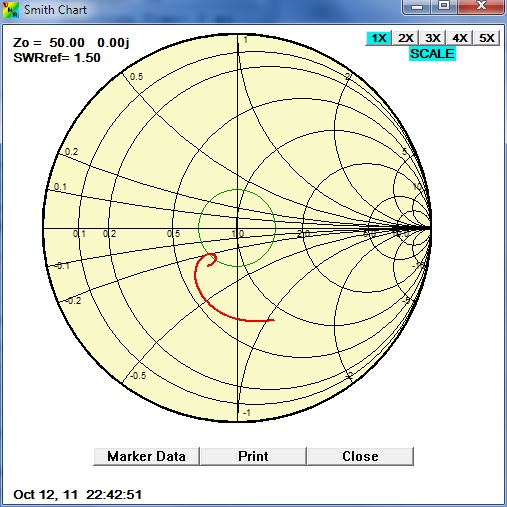
The smith chart below shows the input impedance with the antenna connected directly to the analyzer. The second chart shows the change in input impedance with an extended (25ft) feedline. The observation that the impendence versus frequency is somewhat similar asside from a rotation around the chart illustrates the the choke is nearly sufficient to "cut off" the sheld dipole arm.


10M RFD with short (6ft) feedline

10M RFD with long (25ft) feedline

I connected up the iCOM IC7000 and verified that it too saw the same SWR as the VNA.

I can foresee that this form of antenna could be quite handy. It is very simple, light weight and easy to put up either as a sloper, flat top, or even a vertical. Other bands will need seperate versions, obvious changes are needed to strengthen the center connection and higher choke inductance is needed, espically at lower bands.

73
VE3IAC

Heathkit HW-12


The Heathkit HW-12A is a single "mono-bander" 80 meter  CW/SSB transceiver with a 200 watts P.E.P.  The "final" power amplifier is based on a pair of 6GE5 tubes.

This transceiver was first introduced in 1966 and was sold until 1974. The HP-23 power supply, which was rebuilt for the SB-101 can be used to put this radio into service.

Heathkit HW-12A

The 6GE5 tube was created for genereal usage as a Beam Power Tube used in horizontal-deflection amplifiers in television receivers of the era.


Heathkit HW-12A Main Tuning and Multifunction Meter


I followed the calibration and alignment procedure outlined in the manual and found the needed adjustments to be clear and straightforward. The is no pesky, final neutralization in this rig and alignment is vastly simplified because the rig only has one band to complete.


Heathkit HW-12A with Tuner, Mic and HP-23 Powersupply

HW-12A ready to go onthe air.

73
VE3IAC

Sunday, October 9, 2011

Heathkit SB-101 makes another QSO!


Heathkit was a significant contributor to the Amateur Radio hobby, their products, in kit form, enabled countless amateurs to explore the hobby in a very important way. Kit building radio equipment was second only to scratch building, but scratch building was a skill that was learned and "progressed towards". The learning's and building enjoyment Heathkit gave us were equaled only by the thrill of operating a radio you could say you understood how it worked.

More information about Heathkit is easily found on the web and you can start at
http://en.wikipedia.org/wiki/Heathkit
http://www.heathkit-museum.com/

Today's radios, are packed full of features in compact spaces, using surface mounted components that are difficult to impossible for the hobbyist to work with in any enjoyable way. Additionally, today's radios are becoming increasingly a product of the software they run and this truly is in the non-enjoyable space.

Even though many Heathkit rigs are more than 40 years old, I think it is easy to understand why these radios are sought after and restored.

SB-101

The SB-101 is a SSB/CW rig manufactured by Heathkit between 1967 to1970. Is is a non solid state (no transistor) tube based radio. The finals are a pair of 6146 tubes and produces about 100 watts PEP output power. The plate voltage in this section in excess of 800 Volts.

SB-101,... at the controls
The controls on the SB-101 are very nice, and when you operate this radio, as with many of this era, you feel engaged and in control. There is something to be said about not "flying by wire".


This radio, that I was able to pick up at a local ham swap meet, was in fine shape. 


SB-101 Inside


The obligatory picture of the innards is to the right. My look inside told me the radio builder paid attention to details and every thing looked in order. The purchase was easy


I did not know it at the time, but I quickly learned that an external supply, the HP-23 is needed to power the radio. Now, I can tell you the sign of a good flea market is one where you can buy a radio on one table and pick up the needed supply at another.
HP-23 Power Supply


I picked up the manual and schematic at http://www.mods.dk/ and started the alignment procedure, the first thing I noticed was the drooping 820V supply. I ordered and installed the HP-23D power supply refurbishment kit from the fine folks at Old Heathkit Parts ( http://www.ultrawebb.com/OHP/index.htm )
 
Below is a picture of the new printed circuit card and components installed in the base of the supply. It replaces all of the electrical parts of the supply except for the mains transformer and choke.
HP-23 Conversion Kit Installed

With this done the 820V supply increased to close to 800V from the 720V previous value. The balance of the alignment was completed and the 40 year old SB-101 easily wallops out a clean 100W on all bands 80M to 10M.

The vintage mic I have is an Astatic "lollipop" D-104 (another flea market item), and once the needed 2pin mic connector was soldered on, and the 9Volt battery was replace, I could see this old radio wanted to get on the air.

Last night I fired out 2 QSO on 40m,...

Amazing! Thanks Heathkit

Wednesday, July 14, 2010

QSL cards for IOTA NA-128

Hi All

QSL cards are in the mail, thanks to all who QSL'd


73 OM

VE3IAC
Adrien