The Yaesu FT101 series radios were met with quick adoption by the Ham community when these radios were introduced in the early 70`s. Since I have no experience with a tube based radio I quickly set my determination on getting one of these rigs. I was interested in seeing what I could learn both in terms of operating a tube rig.
I was able to pick up at a local flea market, a FT-101E which was in need of a little work.

First Impressions
Simply stated `Very solid`, this little rig weighs in as heavy as the FT2000D, largely due to the built in transformer which supports providing the 230W of input power to the finals as well as the remainder of the radio. It is safe to say that these radios are hand crafted, which is simply great for the operator who wants to get his `hands on`, and potentially also shocked, but lets hope that does not happen.
First Steps
The seller provided me with a set of crystals 3 6JS6C spare finals, with 2 already installed in the Radio and 1 12BY7A Driver. I installed the crystals and the 1 driver tube, plugged it in to AC source and hoped for the best. I was also supplied with a complete hard copy of the service manual which is very complete and has all the information I will likely need.
From here on in, I have structured this post into three sections. Things what work, Things that do not and repairs I have done.
Things that work
The rig powered up, fine, and most things looked O.K. on first glance. Lots of audio, and some signals could be had on LSB. Heaters did light up as expected. All lamps worked as expected, and the cooling fan for the finals ran nicely.
- 80M/40M/20M/15M/11M/10M Rx
- Preselector
- WWV 10MHz Rx
- 100 and 25kHz markers
- Bias Adjust; Bias current responds smoothly with adjustment of bias control variable resistor VR1. Bias was set to 60mA as required.
Things that still do not appear to work as expected
The vernier slips as the main tuning dial is rotated.
Meter function switch contacts are poor.
Items worked on
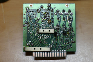
- Fixed: Low sensitivity on bands that work. Don't ask me why but I tested PL4, the lamp that is in series with the signal path in from the antenna connector. It was not open, but resistance was north of 100 ohms. The replacement part form the local hardware store also PN 1815 was about 5 ohms. Sensitivity is much better with the replacement part.


- Fixed: USB is "as dead as a doornail". LSB worked fine but USB was not operational. I tracked the lack of any signal reception to the Q3 on the modulator unit. There was a repair attempted and this was part of the hint. I noticed that the transistor was not the part called for in the schematic. The design part 2SC372Y was replaced by a 2SC383. Q3, Q5 abd Q6 are all the same device, is responsible for the generation of USB, LSB and CW/AM carrier inputs. I moved the Q6 part too the position of the Q3 and this fixed the USB mode problem. I replaced Q6 with a silicon part 2N3904. Now all modes work, LSB. USB, Tune, CW and AM.
- Alignment: Bias. Set Bias to 60mA as required. There is some play in the meter function switch which makes getting a reading a bit awkward.

- Alignment: ALC level. ALC level was low, at about 0.3, Adjusted Level control to set ALC level to 0..5 as required in the alignment procedure.
No comments:
Post a Comment