Showing posts with label VE3IAC Station. Show all posts

Friday, May 24, 2013

The New QTH

Hi  OM

Well, this has been a long time coming but we have moved from the cramped noisy city to a mode spacious and quiet QTH.

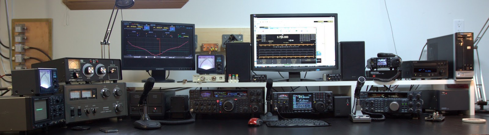
The station has been setup,  a quick run down of the shack is
  • Palstar AT1500CV Tuner
  • Kenwood SM-230 Station Monitor
  • Kenwood TL-922A Linear
  • Yaesu FT2000D
  • iCOM 756 Pro-III
  • Kenwood TS-850S
  • iCOM 7000 (for 2m)

The Radio Shack

The QTH is 33 rural acres south of Ottawa and the power line noise of the old QTH is no longer a problem.

Country QTH

The lot is 450ft wide by 1km deep, so there is plenty of space to imagine and work with.

I am really looking forward to getting back on the air.

73
Adrien
VE3IAC

Monday, March 15, 2010

S9+ Power Line Noise - one solution

Power line noise can make a real train wreck out of an otherwise very interesting and compelling hobby. Several hams are fortunate enough to be able to solve power line noise problems at the source. In other cases where it is not possible to locate and fix the offending source the ham is left to other solutions. This post describes how I use the DX Engineering Receive Antenna Variable Phasing Controller - DXE-NCC-1 to combat the power line noise I get in my shack.

I have written several posts on my ongoing power line noise and these may be of interest.

The image below shows the NCC-1 on my radio desk. It is not as small as one might expect as compared to perhaps a related product from MFJ, but it is a nice looking accessory, and fits in very well.

The all controls are easily manipulated due to their generous size. In particular the Phase control knob, which is the large dial on the right reflects it's importance in the entire concept, second only to the balance control.

From Left to right
  • Attenuation A, sets the attenuation for the signal form Antenna port A. 4 settings are available, 0dB, -10dB, -20dB and -30dB. In my setup I use this port to accept the Rx RF out from the FT2000D
  • Balance controls the mix level of the attenuated antenna signals. Full left to full right provides 10dB of balance control. If more is needed then the switched attenuators (to the left and right are engaged)
  • Attenuation B, sets the attenuation for the signal form Antenna port B. 4 settings are available, 0dB, -10dB, -20dB and -30dB. In my setup I use a secondary un tuned (arbitrary length) dipole fit up in the attic.
  • Phase, Controls the relative phase of the attenuated and balanced antenna port signals at the combiner in the unit.
The unit is bypassed when the Rx port on the FT2000 is not engaged. One push of the Rx port button on the FT2k sends the FT2k main antenna signal to the antenna A input on the NCC-1, where it is balanced and added to a phase adjusted to the NCC-1 antenna B input. Antenna B input comes from the simple noise `Dipole`. The hopefully improved sum is sent back to the FT2k.


The external housing, internal PCB and layout, component placement all point to a design which appears well thought out and mature.

The rear apron has inputs for the 2 input antenna ports, one RF output port and a 12V DC input power plug.


How well does it work?

Before I describe the plot below, I should write a few words on tuning.

The main outdoor 80m windom antenna is much larger than the 20ft noise dipole in the attic and so the signal from the main antenna 20dB stronger. I usually go through the following steps.
  1. Set the main antenna attenuator (A) to -30dB. and place the balance control (BAL) to center.
  2. Set the noise antenna attenuator (B) for 0dB and make a note of the noise level on the S meter and then set the attenuator (B) to -30dB.
  3. Advance the main antenna attenuator (A) until approximately the same noise level is seen on the S-meter. This typically results on a setting of -20dB.
  4. Advance the noise attenuator (B) to 0dB.
Now what is left is to fine tune to cancel out the power line noise.
  1. Usually a sweep of the phase control will show a dip in S meter and audio noise level. As best as possible set the phase at this value.
  2. Now a sweep of the balance will also locate a deeper dip in noise level.
  3. A second iteration of one more phase adjustment and balance will usually locate a sharp cancellation setting.
Like tuning up the old tube rigs, it takes some time to become accustom to the above procedure, but practice yields repeatable results.

The plot below is a log of my S-Meter while a QSO I was monitoring was in progress.
  • The first block at the left of the trace shows a S9+ noise level with the noise canceller disabled.
  • Shortly after, the S-meter readings drop to about S3, this is when I engaged the canceller.
  • During the main part of the plot, you can see a speech pattern from the QSO, including the S3 noise levels between his words.
  • Near the 75% mark, you can see where I again disabled the noise canceler and the noise level returns to the depressing S9+ level


As you can expect, copy is next to impossible with the canceler not engaged. The QSO is below the noise level. Engaged is a very different story, although the cancellation is not perfect, the QSO is 4 to 5 S-units above the cleaned up noise floor and is very copyable.


73
Adrien
VE3IAC

Sunday, September 13, 2009

A New Old FT-101E

Well there simply must be at least 1 boat anchor in every shack, and being somewhat new to the hobby I had the pleasure of needing to `go out and get one`.

The Yaesu FT101 series radios were met with quick adoption by the Ham community when these radios were introduced in the early 70`s. Since I have no experience with a tube based radio I quickly set my determination on getting one of these rigs. I was interested in seeing what I could learn both in terms of operating a tube rig.

I was able to pick up at a local flea market, a FT-101E which was in need of a little work.


First Impressions

Simply stated `Very solid`, this little rig weighs in as heavy as the FT2000D, largely due to the built in transformer which supports providing the 230W of input power to the finals as well as the remainder of the radio. It is safe to say that these radios are hand crafted, which is simply great for the operator who wants to get his `hands on`, and potentially also shocked, but lets hope that does not happen.


First Steps

The seller provided me with a set of crystals 3 6JS6C spare finals, with 2 already installed in the Radio and 1 12BY7A Driver. I installed the crystals and the 1 driver tube, plugged it in to AC source and hoped for the best. I was also supplied with a complete hard copy of the service manual which is very complete and has all the information I will likely need.

From here on in, I have structured this post into three sections. Things what work, Things that do not and repairs I have done.

Things that work

The rig powered up, fine, and most things looked O.K. on first glance. Lots of audio, and some signals could be had on LSB. Heaters did light up as expected. All lamps worked as expected, and the cooling fan for the finals ran nicely.

  • 80M/40M/20M/15M/11M/10M Rx
  • Preselector
  • WWV 10MHz Rx
  • 100 and 25kHz markers
  • Bias Adjust; Bias current responds smoothly with adjustment of bias control variable resistor VR1. Bias was set to 60mA as required.


Things that still do not appear to work as expected

The vernier slips as the main tuning dial is rotated.
Meter function switch contacts are poor.


Items worked on

  • Fixed: Low sensitivity on bands that work. Don't ask me why but I tested PL4, the lamp that is in series with the signal path in from the antenna connector. It was not open, but resistance was north of 100 ohms. The replacement part form the local hardware store also PN 1815 was about 5 ohms. Sensitivity is much better with the replacement part.
  • Fixed: USB is "as dead as a doornail". LSB worked fine but USB was not operational. I tracked the lack of any signal reception to the Q3 on the modulator unit. There was a repair attempted and this was part of the hint. I noticed that the transistor was not the part called for in the schematic. The design part 2SC372Y was replaced by a 2SC383. Q3, Q5 abd Q6 are all the same device, is responsible for the generation of USB, LSB and CW/AM carrier inputs. I moved the Q6 part too the position of the Q3 and this fixed the USB mode problem. I replaced Q6 with a silicon part 2N3904. Now all modes work, LSB. USB, Tune, CW and AM.
  • Alignment: Bias. Set Bias to 60mA as required. There is some play in the meter function switch which makes getting a reading a bit awkward.
  • Alignment: ALC level. ALC level was low, at about 0.3, Adjusted Level control to set ALC level to 0..5 as required in the alignment procedure.

Monday, March 9, 2009

R8 HF Vertical

(http://www.lairdtech.com/)

Recentl
y I picked up a second hand Cushcraft R8 vertical.

I had the folliwing goals in mind
  1. Vertical
  2. Multiband
  3. No radials
  4. Low take off angle
  5. WARC bands included
  6. Possibility of field day operation
  • Vertical
Given the layout of the my house's lot, a second antenna would be easier to install if it were a vertical. Also my existing antenna is a 80M to 6M Windom Buxcomm model 802136 and I am intersted in having a vertical to compare. I'll likely never setup a beam so this second antenna will be it.
  • Multiband
Multiband is tablestakes, because I need to able to get as much out of an antenna as I can. The R8 is one among very few 8-banders covering from 40 to 6m, WARC included.
  • No radials
I like the idea of no radials, mainly because of the ease of installation and flexibility of installation lacation. R8 uses 7 49in stainless radial rods at the base of the antenna.
  • Gain and Low take off angle
DX, DX, DX, Low take off angle is important for DX work. With its low radiation angle R-8 vertical should have distinct advantages compared to my windom. The 360 degree coverage should be nice as well.
  • Power Handling
The R8 supports 1500W which is plenty for my FT2000D which is a 200W rig.
  • WARC bands included
I enjoy digital operation and I often find that the WARC bands have activity, but the Windom antenna does not tune up on 30m for example.
  • Possibility of field day operation
The R8 could be used in field day operations but due to its weight it is not easy to get it down without help. Once installed, I think its up there for the long run.

Considerations
  • Guying
I did guy the antenna down to three points.
  • Grounding
I have grounded the mast to a single 8ft ground rod with a run 10ft run of #6 ground wire.

Specifications

Model R8
Gain, dBi 3

Height, m. 8.7

Horizontal rad, deg 360

Power Rating, Watts CW 1500

Vertical Radiation Angle, deg. 16

Band / Bandwidth (kHz) 10m >1500

Band / Bandwidth (kHz) 12m >100

Band / Bandwidth (kHz) 15m >450

Band / Bandwidth (kHz) 17m >100

Band / Bandwidth (kHz) 20m >350

Band / Bandwidth (kHz) 30m >50

Band / Bandwidth (kHz) 40m >150

Band / Bandwidth (kHz) 6m >1500

VSWR at resonance (typical) 1.3:1

Weight, kg. 10.5

Wind Survival kph. 120


The Cleanup

Since the antenna was second hand I had quite a time cleaning up the antenna and setting all the element lengths to the specification.
  • I cleaned up external surfaces with a combination of steel wool and lots of work. With this I was able to restore the antenna to showroom look, shine and all.
  • The short 6" terminal tuning stubs rods were oxidized such that it was impossible to remove these from the longer stub tubes. I did confirm that all stubs were all stuck in place at the right lengths.
  • I opened the R8 matching network box and confirmed that there were no mechanical failures of the components inside. A mechanical inspection was complete.
  • I completely assembled the antenna indoors to see the antenna fit together and confirmed nothing was mechanically broken or missing.
Installation Preparation
  • I decided to install the vertical on the corner of my backyard shed. A 2 in pipe was installed up through the roof of the shed.
  • I decided to guy the antenna from the initial start
  • I placed a 1:1 choke at (near) the antenna.
  • Grounding, 8ft copper clad steel rod at base of mast
  • Feed line, was 100ft RG/8
  • Lightning arresor, was placed at the house
Operation
  • All bands tune up and better than 1.5:1 on all but the high end of 40m.
  • Have not tried to see how it tunes on 6m.

Thursday, November 13, 2008

VE3IAC Station

---- QSL cards


I have finally setup myself with QSL cards. The design was made up in PowerPoint and I print up 4 to a sheet and then slice & dice. This may be the long and hard way, but for now this is it. I've started sending cards to as many of my QSO's that use direct. For the moment, I'm quite interested in gathering these tokens of the great distances I've been able to communicate.

Thanks to all to QSL back.


---- Updated Shack


In the fall I updated my radio shack to provide for a bit more desk space. Radios are the Yaesu 200w FT2000D, truly a basestation radio, the I-COM 7000 a nice 100W all mode HF/VHF/UHF mobile transceiver, and a classic, not quite a boat anchor, Kenwood TS-850AT.

---- FT2000D


I purchased my FT2000D late summer 08. I spent many hours pouring over as much material as I could find to help me make this decision knowing that this would be the radio I'd have for many years. I also looked at the IC756PROIII. In the end I decided to go with the FT2000D.