1. Install the modeling tool 4NEC2 which is available at http://home.ict.nl/~arivoors/ . I run XP and Vista and have no problems with the program. I hope you do not either.
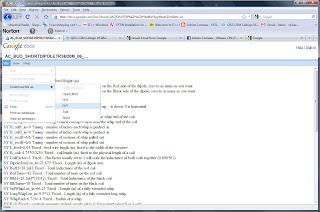 2. I have posted an example file at my documents at the following link. Go to the link and download the model file and save it to your pc where you can find it later. Save it as a plain text file.
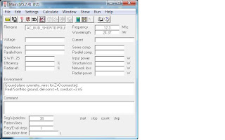 3. launch 4NEC2 and load the file from step 2. There may be a few parameters you have to set
Settings->CharImp set to 25 ohms
Because, when this antenna resonates is close to 25ohms, this implies that you have a 2:1 balun like the budipole TRSB and it is set to 2:1.
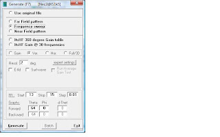 4. Lets run it. Select Calculate->Nec Output data then select a frequency sweep from 13 to 15MHz.
The output should look like this.
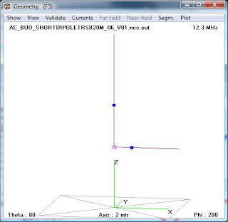 Geometry shows a vertical with a loading coil set mid way.
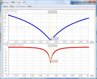 Sweep shows resonance at 14.05MHz, which is very nice for PSK.
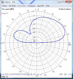 The antenna pattern shows a modest directional pattern, with a lower takeoff angle than can be obtained with a dipole at any reasonable height.
Now lets take a look at the file,
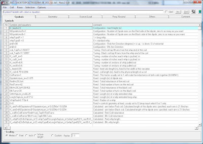
H_feed=2.5 Configuration - feed Height (m) - set this to the height of the versatee
NDipoleArmsR=3 Configuration - Number of Dipole arms on the Red side of the dipole, zero to as many as you want. These things (link), In general you want to get the coil away from the versatee. I think this leads to a better pattern but I cant prove it.
NDipoleArmsB=1 Configuration - Number of Dipole arms on the Black side of the dipole, zero to as many as you want. Same as above
whipTypeR = 1 1 = long whip
whipTypeB = 0 0 = standard whip
Indicate the type of whips you are using, I use a long whip for the vertical, more is better. and a short or normal whip for the counterpoise, the long one places a lot of torque on the versatee.
phiR=90 Configuration - Red Arm Direction (degrees) + is up, - is down, 0 is horizontal
phiB=0 Configuration - Blk Arm Direction
These are angles in degrees, 0 is horizontal, 90 is straight up, so you can see the red (R) arm is up, and the black (B) is horizontal. You can specify what ever angles you want. 0 & 0 makes a horizontal dipole!
coil_TapR=2.392877 Tuning - Red coil tap # turns from the whip end of the coil
coil_TapB=11.10957 Tuning - Black coil tap # turns from the whip end of the coil
OK, these numbers are solved for by the program once you decide what resonant frequency you want. Rounded to the integer, they indicate where to tap the coil. I can not promise the solved solution will be bang on but this is a starting point.
H_cutR_in=0 Tuning - number of inches each whip is pushed in
H_cutB_in=0 Tuning - number of inches each whip is pushed in
This specifies the number of inches each whip is pushed in by. Usually I set 0, but in the budipole examples some times the documents specify a few inches here and there.
H_sectR=6/6 Tuning - number of sections of whip pulled out
H_sectB=6/6 Tuning - number of sections of whip pulled out
These specify the number of extended whip segments.
The items below are fixed and relate to the geometry of the system components.
L_feed=0.05 Fixed - feed wire length (m), fixed to the width of the versatee
H_coil=4.75*0.0254 Fixed - coil length (m), fixed to the physical length of a coil
CoilFactor=1 Fixed - This factor usually set to 1 will scale the inductance of both coils together
DipoleArmLen_in=21.875 Fixed - Length (in) of dipole arm
RedH=28.2uH Fixed - Total Inductance of the red coil
RedTurns=42 Fixed - Total number of turns on the red coil
BlkH=28.2uH*(38/42) Fixed - Total Inductance of the black coil
BlkTurns=38 Fixed - Total number of turns on the black coil
StdWhipLen_in=66.25 Fixed - Length (in) of a fully extended whip
LongWhipLen_in=9.5*12 Fixed - Length (in) of a fully extended long whip
WhipRad=6.719e-4 Fixed - Radius of a whip
K=0 Fixed = controls geometry at feed, usually set to 0, binary input select 0 or 1 only.
OK this parameter is rather nutty, but it controls the geometry details at the versatee, I'm not sure how to explain it, 0 is the right value.
These are the calculated parameters of the model based on your inputs and the fixed values above.
H_armR=(NDipoleArmsR*DipoleArmLen_in*0.0254)+1*0.0254 Calculated - arm below Red coil, Calculated length of the dipole arms specified, each arm is 21.8inches
H_armB=(NDipoleArmsB*DipoleArmLen_in*0.0254)+1*0.0254 Calculated - arm below Black coil, Calculated length of the dipole arms specified, each arm is 21.8inches
L_coilR=CoilFactor*RedH*coil_TapR/RedTurns Calculated - Red Coil Inductance
L_coilB=CoilFactor*BlkH*coil_TapB/BlkTurns Calculated - Blk Coil Inductance
H_whipR=((StdWhipLen_in*(1-whipTypeR)+LongWhipLen_in*(whipTypeR))*H_sectR-H_cutR_in)*0.0254 Calculated - Red whip length
H_whipB=((StdWhipLen_in*(1-whipTypeB)+LongWhipLen_in*(whipTypeB))*H_sectB-H_cutB_in)*0.0254 Calculated - Blk whip length
So, you should be able to adjust the number of accessory arms, the whip types, the angles of the arms etc.
The trick is getting it to solve for the tap positions. You do this with the following solver in 4NEC2.
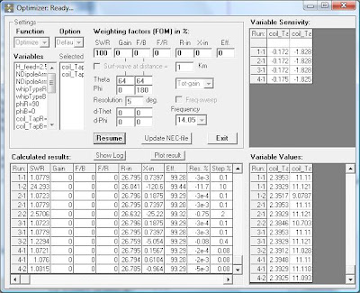
Above is the solution for 14MHz resonance. How about 7.07MHz?
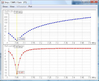
The model predicts red Coil 42 from the whip end, i.e. the entire coil, and the black 31.6 turns from the whip.
I'll have to give this a try outside and see how close it is to reality I expect some adjustmnts to the model will be needed. Only through doing enough if these I'm learning through trial and error how the model needs to be set for things like the wire diameter whcich has a profound effect on the predictions.
73
Adrien