Tuesday, October 18, 2011

10M band RFD Resonant Feedline Dipole


I am interested in experimenting with antenna designs, and those that have properties which make them useful for temporary field usage are interesting.

This post is about the construction and measurements of a Resonant Feedline Dipole cut for the 10M band.

The resonant feedline dipole is simply described as an open ended 50ohm coaxial section with its center conductor extended a measured distance, and with a common mode choke placed the same  measured distance back from the "open end".

The central feed point of the dipole is the open end of the coax . The extended center conductor acts as one half of the dipole. The coax's shield from the "open end" back to the common mode choke acts as the other half of the dipole. Power is delivered to the feed point within the coax its self in the usual way coax transfers power. The choke's distance and extended conductor's length are selected in the usual way.

10M Resonant Feedline Dipole
The picture above shows the basic structure. The SMA connector is the coax connection. The coax used is RG-174. After some arbitrary length a snap on choke is used to create the common mode choke. After an additional 7ft 8.25in of RG-174 the coax end is reached. At this point the center conductor is extended with a 7ft 8.25in length of regular 18AWG covered stranded wire.

Center with temporary strengthening strain relief.
5 turn Choke
 
I used a USB based VNA ( http://www.arraysolutions.com/Products/vna2180.htm ) to measure the antenna's feed point.

VNA 2180

Full Sweep 1MHz to 30MHz showing resonance in 10M band
SWR is the red line in the above figure and the length 7ft 8.25in resulted in resonance being placed in the middle of the 10M band.

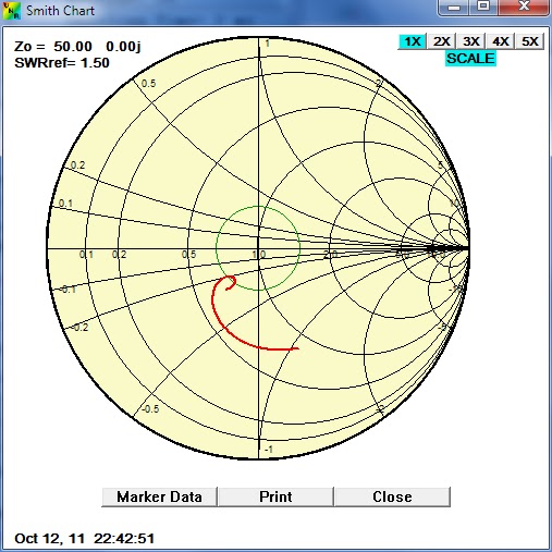
The smith chart below shows the input impedance with the antenna connected directly to the analyzer. The second chart shows the change in input impedance with an extended (25ft) feedline. The observation that the impendence versus frequency is somewhat similar asside from a rotation around the chart illustrates the the choke is nearly sufficient to "cut off" the sheld dipole arm.


10M RFD with short (6ft) feedline

10M RFD with long (25ft) feedline

I connected up the iCOM IC7000 and verified that it too saw the same SWR as the VNA.

I can foresee that this form of antenna could be quite handy. It is very simple, light weight and easy to put up either as a sloper, flat top, or even a vertical. Other bands will need seperate versions, obvious changes are needed to strengthen the center connection and higher choke inductance is needed, espically at lower bands.

73
VE3IAC

Heathkit HW-12


The Heathkit HW-12A is a single "mono-bander" 80 meter  CW/SSB transceiver with a 200 watts P.E.P.  The "final" power amplifier is based on a pair of 6GE5 tubes.

This transceiver was first introduced in 1966 and was sold until 1974. The HP-23 power supply, which was rebuilt for the SB-101 can be used to put this radio into service.

Heathkit HW-12A

The 6GE5 tube was created for genereal usage as a Beam Power Tube used in horizontal-deflection amplifiers in television receivers of the era.


Heathkit HW-12A Main Tuning and Multifunction Meter


I followed the calibration and alignment procedure outlined in the manual and found the needed adjustments to be clear and straightforward. The is no pesky, final neutralization in this rig and alignment is vastly simplified because the rig only has one band to complete.


Heathkit HW-12A with Tuner, Mic and HP-23 Powersupply

HW-12A ready to go onthe air.

73
VE3IAC

Sunday, October 9, 2011

Heathkit SB-101 makes another QSO!


Heathkit was a significant contributor to the Amateur Radio hobby, their products, in kit form, enabled countless amateurs to explore the hobby in a very important way. Kit building radio equipment was second only to scratch building, but scratch building was a skill that was learned and "progressed towards". The learning's and building enjoyment Heathkit gave us were equaled only by the thrill of operating a radio you could say you understood how it worked.

More information about Heathkit is easily found on the web and you can start at
http://en.wikipedia.org/wiki/Heathkit
http://www.heathkit-museum.com/

Today's radios, are packed full of features in compact spaces, using surface mounted components that are difficult to impossible for the hobbyist to work with in any enjoyable way. Additionally, today's radios are becoming increasingly a product of the software they run and this truly is in the non-enjoyable space.

Even though many Heathkit rigs are more than 40 years old, I think it is easy to understand why these radios are sought after and restored.

SB-101

The SB-101 is a SSB/CW rig manufactured by Heathkit between 1967 to1970. Is is a non solid state (no transistor) tube based radio. The finals are a pair of 6146 tubes and produces about 100 watts PEP output power. The plate voltage in this section in excess of 800 Volts.

SB-101,... at the controls
The controls on the SB-101 are very nice, and when you operate this radio, as with many of this era, you feel engaged and in control. There is something to be said about not "flying by wire".


This radio, that I was able to pick up at a local ham swap meet, was in fine shape. 


SB-101 Inside


The obligatory picture of the innards is to the right. My look inside told me the radio builder paid attention to details and every thing looked in order. The purchase was easy


I did not know it at the time, but I quickly learned that an external supply, the HP-23 is needed to power the radio. Now, I can tell you the sign of a good flea market is one where you can buy a radio on one table and pick up the needed supply at another.
HP-23 Power Supply


I picked up the manual and schematic at http://www.mods.dk/ and started the alignment procedure, the first thing I noticed was the drooping 820V supply. I ordered and installed the HP-23D power supply refurbishment kit from the fine folks at Old Heathkit Parts ( http://www.ultrawebb.com/OHP/index.htm )
 
Below is a picture of the new printed circuit card and components installed in the base of the supply. It replaces all of the electrical parts of the supply except for the mains transformer and choke.
HP-23 Conversion Kit Installed

With this done the 820V supply increased to close to 800V from the 720V previous value. The balance of the alignment was completed and the 40 year old SB-101 easily wallops out a clean 100W on all bands 80M to 10M.

The vintage mic I have is an Astatic "lollipop" D-104 (another flea market item), and once the needed 2pin mic connector was soldered on, and the 9Volt battery was replace, I could see this old radio wanted to get on the air.

Last night I fired out 2 QSO on 40m,...

Amazing! Thanks Heathkit